Highlight:
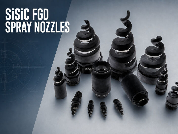
SiSiC Desulfurization Spray Nozzle for Wet FGD Systems
SiSiC Desulfurization Spray Nozzle for Wet FGD Systems
A SiSiC desulfurization spray nozzle distributes limestone, lime, or another alkaline scrubbing slurry inside a wet flue gas desulfurization system.
The nozzle is continuously exposed to slurry containing suspended solids. Wear normally develops inside the flow passage, around changes in direction, and at the outlet. As these areas change, the nozzle may still appear complete from the outside while its flow and spray characteristics have already begun to shift.
SiSiC, also known as RBSiC or reaction-bonded silicon carbide, provides a dense ceramic structure with resistance to abrasion, erosion, and many corrosive media. It is used for wet FGD spray nozzles where conventional materials may wear rapidly in contact with circulating slurry.
Spiral, single-direction, and double-direction configurations are available. The correct structure should be selected according to the required flow rate, spray angle, operating pressure, slurry properties, and absorber layout.
Product Short Description:
ELACERA SiSiC desulfurization spray nozzles are used in wet FGD systems handling abrasive scrubbing slurry. We can manufacture spiral, single-direction, and double-direction nozzle configurations to approved drawings, samples, and spray requirements.

Why Do FGD Spray Nozzles Wear?
Wet FGD slurry is not a clean liquid.
Solid particles repeatedly pass through the nozzle at operating velocity. Whenever the flow accelerates or changes direction, particles may strike the internal surface and gradually remove material.
Typical problems include:
- Erosion of the internal flow passage
- Enlargement or deformation of the outlet
- Local wear around directional changes
- Slurry build-up or partial blockage
- Changes in spray distribution
- Chemical attack from the scrubbing medium
- Damage around connections during installation
- Cracking or chipping caused by mechanical impact
For this reason, selecting a nozzle only by its overall dimensions is not sufficient. The internal structure and spray duty must also match the existing system.
Available Nozzle Configurations
SiSiC Spiral Nozzle
A SiSiC spiral nozzle uses a continuous external spiral profile to divide and distribute the slurry.
The exposed spiral structure provides a relatively open flow path compared with nozzle designs that rely on an internal vane. This is useful when the liquid contains suspended particles and internal obstruction is a concern.
However, a spiral design does not make the nozzle completely immune to blockage. Particle size, slurry condition, upstream screening, flow rate and available pressure still need to be reviewed.
The spiral profile, body diameter, connection, and overall length can be manufactured according to the approved drawing.
Single-Direction Nozzle
A single-direction nozzle discharges the slurry toward one specified direction. Its outlet orientation must match the spray header and absorber arrangement.
The following details are particularly important:
- Outlet direction
- Installation angle
- Connection position
- Available clearance
- Required spray coverage
- Orientation after installation
A dimensional drawing should clearly show both the connection and the discharge direction.
Double-Direction Nozzle
A double-direction nozzle incorporates two directional outlets within one ceramic body.
This configuration may be considered when the absorber design requires slurry to be directed toward two areas from one connection position. Outlet size, outlet angle, and flow distribution must be confirmed from the approved nozzle design.
The two outlets should not be assumed to provide equal flow unless this has been established by the hydraulic design or performance test.
Why Use RBSiC or SiSiC?
RBSiC is produced by forming a silicon carbide and carbon body and then infiltrating it with silicon. The reaction creates additional silicon carbide while some free silicon remains in the finished material.
This process produces a dense ceramic with zero open porosity according to the supplier’s reference data.
For FGD nozzle applications, the relevant material characteristics include:
- Resistance to abrasive slurry erosion
- Dense structure with low liquid penetration
- Dimensional stability
- Resistance to many chemical environments
- Ability to form customized nozzle geometries
- Smooth ceramic flow surfaces after finishing
Chemical compatibility must still be checked against the actual slurry composition. “Silicon carbide” alone is not a complete material specification because RBSiC, SSiC, NBSiC, and other grades have different compositions and properties.
Typical RBSiC (SiSiC) Material Data
| Item |
Supplier Reference Value |
| Material grade |
RBSiC / SiSiC |
| SiC content |
85% |
| Free silicon content |
15% |
| Density |
3.02 g/cm³ |
| Open porosity |
0% |
| Maximum material service temperature |
1380°C |
| Bending strength at 20°C |
250 MPa |
| Modulus of elasticity at 20°C |
330 GPa |
| Thermal conductivity at 1200°C |
45 W/m·K |
| Coefficient of thermal expansion |
4.5 × 10⁻⁶/K |
These values are taken from the supplier’s material data and describe the RBSiC material rather than the complete nozzle system.
The actual allowable operating temperature may be limited by the connection, seal, surrounding equipment, thermal cycling or slurry conditions. Final values should be included in the approved technical specification when they are required for acceptance.
Spray Duty Determines the Nozzle Geometry
Two nozzles with similar external dimensions may have different flow and spray performance.
The internal passage, outlet size, spiral profile, outlet direction, and connection all affect how the slurry leaves the nozzle. A replacement nozzle should therefore be matched using both dimensional and operating information.
Important selection data include:
- Required flow rate
- Operating pressure
- Spray pattern
- Spray angle
- Required droplet size
- Slurry density
- Slurry viscosity
- Solids concentration
- Maximum particle size
- Required free passage
- Installation direction
- Connection dimensions
If the original spray data are unavailable, the existing nozzle drawing, equipment manual, and an unused sample should be reviewed together.
Custom Manufacturing from Drawings or Samples
SiSiC FGD nozzles can be manufactured according to an approved drawing or an existing sample.
An unused sample is preferable because a nozzle that has already been in service may have dimensional changes caused by erosion. The outlet and internal passage are particularly vulnerable.
When only a used sample is available, the review should distinguish between:
- Original manufactured dimensions
- Areas enlarged by slurry erosion
- Accidental mechanical damage
- Slurry deposits that reduce the opening
- Connection surfaces unaffected by wear
Copying a worn outlet without correction may also reproduce the wear-related error.
Connection and Installation Details
The connection must match the existing spray header and maintain the intended nozzle orientation.
Depending on the approved design, the nozzle may use a threaded, cylindrical, flanged or other customized connection. Never select the connection type from an external photograph alone.
Before production, confirm:
- Thread specification or flange dimensions
- Connection length
- Sealing surface
- Installation direction
- Required tightening method
- Available installation space
- Ceramic edge protection during assembly
Ceramic nozzles should be handled carefully during installation. Excessive mechanical force or impact can damage the connection or exposed ceramic edges.
Manufacturing and Inspection
The drawing, material grade, and critical dimensions should be confirmed before production.
Typical inspection items include:
- Overall dimensions
- Connection dimensions
- Outlet size and direction
- Spiral profile or directional structure
- Accessible internal passage dimensions
- Surface condition
- Cracks, chips, and edge damage
- Quantity and part identification
- Agreed material documentation
Hydraulic flow testing and spray-pattern testing are separate from ordinary dimensional inspection. If these tests are required, the test liquid, pressure, flow tolerance, spray angle, and acceptance method should be agreed before quotation.
Typical Applications
SiSiC desulfurization spray nozzles can be used in wet scrubbing systems for:
- Coal-fired power plants
- Industrial boilers
- Cement kiln exhaust treatment
- Waste-incineration plants
- Metallurgical plants
- Chemical processing facilities
- Other industrial wet gas-cleaning systems
The actual slurry composition and spray requirements vary between systems. Each project should therefore be reviewed separately.
Information Required for Quotation
- Please provide as much of the following information as possible:
- Nozzle drawing or dimensional sketch
- Existing nozzle sample
- Required nozzle configuration
- RBSiC or SiSiC material requirement
- Overall dimensions
- Internal passage and outlet dimensions
- Connection type and dimensions
- Required quantity
- Flow rate
- Operating pressure
- Spray pattern
- Spray angle
- Droplet-size requirement
- Slurry composition
- Solids concentration
- Slurry density and viscosity
- Maximum particle size
- Operating temperature
- Existing wear or blockage problem
If some information is unavailable, provide the original equipment reference and photographs of the existing nozzle installation.
Frequently Asked Questions
Are SiSiC and RBSiC the same material?
The names are commonly used for reaction-bonded or silicon-infiltrated silicon carbide. The final chemical composition and technical data should still be confirmed in the approved material specification.
Which nozzle configuration should be selected?
The choice between spiral, single-direction, and double-direction structures depends on the absorber arrangement, spray direction, flow rate, pressure, and required coverage.
Does an open spiral structure completely prevent blockage?
No. Its relatively open passage can reduce internal obstruction, but blockage also depends on particle size, slurry condition, upstream screening, and system operation.
Can a replacement nozzle be manufactured from a sample?
Yes. An unused sample is preferred. If the sample has already been used, worn areas must be identified before copying the dimensions.
Can the flow rate and spray angle be customized?
The nozzle can be manufactured according to confirmed flow and spray requirements. Hydraulic testing requirements and acceptance tolerances should be agreed before production.
Does 1380°C represent the allowable FGD operating temperature?
No. It is the supplier’s maximum reference temperature for the RBSiC material. The actual nozzle operating limit also depends on thermal cycling, connections, seals, slurry conditions, and surrounding equipment.
How long does a SiSiC FGD nozzle last?
Service life depends on slurry composition, solids concentration, particle size, flow velocity, pressure, operating hours, nozzle geometry, and maintenance. A fixed lifetime should not be promised without operating data.
Request a Technical Review
Send us the existing nozzle drawing, sample information, and wet FGD operating conditions. We will review the SiSiC material, nozzle configuration, connection dimensions, and inspection requirements before preparing the technical quotation.
ELACERA | Wear Protection Solutions

 Your message must be between 20-3,000 characters!